 What is a patch cable? Patch cables are short flexible cables that make interconnects between network ports. They are commonly used in horizontal copper cabling installations. The origin of the word "patch cable" goes all the way back to the beginning of the telephone system, where there was an operator at a switchboard who would route or "patch" calls from one person to another. As the computer industry evolved, cables that make network interconnects became known as patch cables because they routed signals from one part of the network to another.
Are patch cables all the same? No. There are many patch cable standards, technologies, and options today. It's important to understand all of them because you are likely going to be the person selecting patch cable for your network. In most cases, a network installer will not choose your patch cabling for you because they don't know what length or color cable you need. An installer also doesn't know what price you're willing to spend on each cable. Here is some information on standards, technology, and options that can help you select the right patch cable for your application.
One of the most recognizable standards found on an Ethernet patch cable is the connector. All patch cables use the RJ-45 connector, or male plug, on each end. RJ-45 stands for registered jack, and 45 is the number that defines the interface standard. The RJ-45 plug has 8 individual contacts with a center locking tab that looks like a large telephone cable.
Regardless of the category of patch cable, they all use a stranded twisted four pair round cable because it is more flexible than other cables. This superior flexibility allows you to dress bundles of cable in data cabinets or at the remote end of a horizontal cabling run going from the wallplate to the desktop or docking station at a user's desk.
Stranded twisted four pair round cable has four twisted pairs, each of which has a specific color to identify each pair. The colored pairs are blue with white/blue, orange with white/orange, green with white/green, and brown with white/brown.

All patch cables are assembled and terminated with "straight through" T568B pinning end to end. T568B is the specific wiring method used in all Ethernet installations end to end. In the image below, you can see the orange pair is mapped with pins 1 and 2 on the RJ-45 plug, the blue pair with pins 4 and 5, the brown pair with pins 7 and 8, and the green pair (sometimes called the split pair) with pins 3 and 6.

The RJ-45 male plug and the female socket are dominant in the Ethernet networking world. This connector follows a strict standard with very tight tolerances that conforms to the IEC 60603-7 standard. The IEC 60603-7 standard covers specific measurements and parameters so that RJ-45 male plugs and RJ-45 female sockets "mate" properly to provide reliable connectivity with little to no loss.
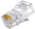
The 8 gold blades coated with 50-um microns of gold on the RJ-45 plug, called the "contact drivers," are what provide reliable connectivity. Gold does not oxidize and offers consistent electrical connectivity. And, since the thickness of the gold is 50-um microns, the user can make up to 750 insertion cycles before the plugs wear out. During termination, it's required that the contact drivers are crimped within a height range of 0.232 inches and 0.242 inches from the plug base to the top of the blade. This height range guarantees that all RJ-45 male plugs and female sockets can mate together and have acceptable interoperability.
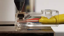
When users think of patch cable technology, they often associate it with a difference in the raw cable used in the patch cable. For example, Category 5e patch cables use Category 5e raw cable, and Category 6 patch cables use Category 6 raw cable. But there is more to the patch cable than just the raw cable. There is a lot of technology inside the RJ-45 plugs on the ends of the patch cable. Just like the raw cable, there are category-grade RJ-45 plugs that each have different internal designs to achieve the desired performance.
Older Category 5 and 5e patch cables use a simpler one-piece RJ-45 design plug, where the 8 individual wires lay side by side in a 1 x 8 pattern. You can see in the image below where the stranded cable would enter inside the back of the plug on the right. About halfway in the plug, the 8 individual wires will begin to line up straight in the same plane, as they come near and under the gold blade contact drivers. So, for a very short distance inside the plug, the four pairs are not twisted. This does not affect performance for these category-grade plugs. These plugs are also easier to terminate.
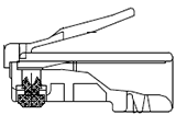
Category 5 Plug Body
Newer Category 6 and even Category 6A plugs still use the same RJ-45 exterior shape. You cannot modify the exterior shape, but the internal cavity of the RJ-45 plug can have modifications. These category 6 and 6A plugs are more complex and typically made with two or three parts. Looking at the images below, you will notice that these plugs have a hollowed out inside. This design feature is extremely important because it allows the 4 twisted pairs from the raw cable to get closer to the gold blades without being untwisted. Keeping the twisted pairs as close to the gold blades as possible improves the NEXT (Near End Crosstalk), an electrical measurement that measures noise from pair to pair within the cable.
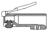 Category 6/6A Plug Body |  Loading Bar |  Pair Separator |
The other internal parts in Category 6 and 6A plugs are loading bars and pair separators. A loading bar is a small piece of plastic polymer with 8 holes that help hold the 4 insulated pairs together, assisting in the termination of the cable assembly. Since the plug body cavity is open inside, trying to correctly push the 4 pairs up in the plug without miswiring is more difficult. The loading bar guarantees that the straight through wiring will be correct. A pair separator is another small piece of plastic polymer that places each twisted pair in its own quadrant, helping to create space or separation between other adjacent pairs in the plug. This space also improves NEXT performance of the final assembly specialty on these higher data grade plugs. Loading bars and pair separators sometimes contain materials with metallic or dense properties that enhance cable performance. The disadvantage of Category 6 and 6A patch cable is the termination usually takes longer, keeping the assembly prices higher than Category 5e patch cables of the same length.
Another noticeable technical design of patch cable plugs is the layout of the 4 pairs. The patch cable must be terminated with the T568B wiring standard, but the layout of the pairs can change to improve performance. It is common for Category 5 and 5e plugs to use a standard 1 x 8 row design. Performance is not as critical for Category 5 and 5e cable, so this simple design is typically used. But, since performance is much more critical for Category 6 and 6A patch cables, a staggered or dual-plane design layout is used in the plug. Wiring layout is another way RJ-45 plug manufacturers can create space between pairs to get higher NEXT performance within the plug of the patch cable.
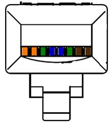 Typical Category 5 Wiring Layout | 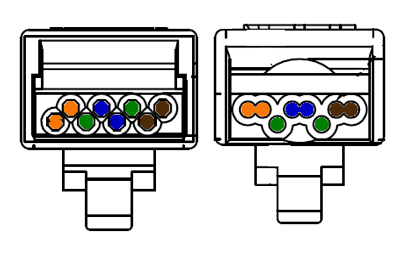 Typical Category 6/6A Wiring Layout |
Patch cable options are probably what most end users consider when they purchase patch cables. Options refer to the patch cable construction and appearance. Patch cable options are almost endless. Some examples of patch cable options include cable construction, termination method, wire gauge, length, and color. These days, patch cables have become a commodity product that is made from countless factories all competing for your money. So many patch cable assembly houses try to make their product different or unique from the competition to try to get you to purchase their patch cables.
This is the basis of what type of raw cable is used in the construction of a patch cable. Common forms of the raw cable are stranded or solid wire with the overall cable being either unshielded or shielded with a PVC or PLENUM-rated jacket. Patch cables are usually raw and unshielded and made with stranded wire and PVC jacketing, but there are some unique applications that require patch cables with solid wire, shielding, and plenum-rated jackets.
Termination method is likely what you will base your patch cable purchase on. There are many types of terminations, including with or without boots, assembled type or molded, with or without snagless boots, and slimline or standard width. Below are some examples:
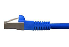 Shielded, SlimLine, Molded with Snagless Boot | 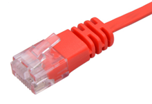 Unshielded, SlimLine, Molded | 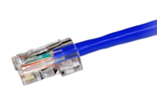 Unshielded, Assembled, with No Boot |
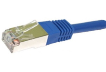 Shielded, SlimLine with a Molded Termination | 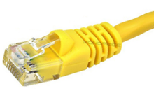 Unshielded, SlimLine, Molded with Snagless Boot | 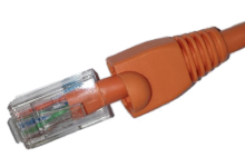 Unshielded, Assembled, with Snagless Boot |
The gauge of the internal wire has a direct impact on the performance of a patch cable. Typically, unshielded patch cables use stranded 24 AWG cables, and shielded patch cables use 26 AWG cables. Although, the latest release of the ANSI/TIA 568.2-D recognizes unshielded patch cables using a smaller stranded 28 AWG core. Using a smaller 28 AWG wire saves space, improves airflow, and enhances port visibility in bundled cable applications. The disadvantage of 28 AWG is higher cable attenuation, or signal loss, that requires you to use shorter cable.
Regardless of cable construction, all suppliers typically offer a wide range of cable lengths and colors. Lengths typically range from 1 foot all the way up to 100 feet, in various increments. Blue is the most common cable color because blue represents data. But often customers select different colors to organize networking ports between departments and even security levels. So having patch cables available in at least 8 to 10 different colors is very common.
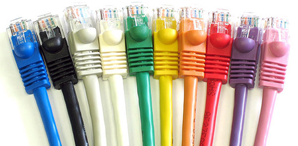
Even though there are many different patch cables on the market, you will most likely select a patch cable that is unshielded stranded PVC assembly. Other variations are available, but they are used in unique applications. And, although different patch cable categories may look the same on the outside, there is a lot of technology inside the cable allowing it to support higher-speed applications. Finally, appearance plays a big role in choosing your patch cables. Many decisions will need to be made for the patch cable termination and color that best meets your application.
It is also important to understand patch cable category ratings. The most common ratings are the Category 5e, Category 6, and Category 6A cables. Each of these support different MHz ratings and applications. Here are two Black Box Explains articles where you can learn more about Category 5 and Category 6 patch cables.

Product Engineer
Steve Molek has 27 years' experience in the cabling and connectivity data communication industry. He started his career as a Technical Support Representative and now works as a Project Engineer for Black Box. As a Product Engineer, his primary focus is evaluating and testing all new cabling and connectivity products for sale by Black Box and training our inside technical support and sales teams. Steve also works directly with our domestic and international OEM suppliers as well as several nationally recognized third-party testing labs. Steve holds a B.S. degree in Mathematics and Computer Science from California University of Pennsylvania and an MBA from Waynesburg University.