It's no surprise that fiber cabling is being used more and more in the data center. This trend has been increasing dramatically over the past few decades. Huge fiber strand cable bundles create the infrastructure backbone of large office parks and business campuses where it eventually enters buildings some point connecting it to the data center and into a data cabinet. Some of these fiber cable bundles can be as small as 12 or 24 strands if that's all you may need or can go up to bundles of 576 strands or more in large complex installations.
As you can begin to imagine, these large fiber cable bundles will eventually make it into the data center and to a data cabinet at some point. Here the cable bundle will terminate to a fiber enclosure and begin to break out into individual pairs for use. The connector of choice these days is the LC connector. The LC is used since it's small and uses a pinch-style locking tab which is similar to the very common RJ-45 used in copper connectivity. But when you begin to install huge fiber cables within a building to a data cabinet, it can get very congested inside the fiber enclosure. For example, a fiber cable bundle of 576 strands terminating with LC connectors will consume 288 LC connectors (288 LCs using a pair of fiber each will use 576 total strands in total). And if that isn't enough, fiber enclosure manufacturers are squeezing as much as 144 fibers in 1 rack unit (1 RU = 1.75"), which means there are 72 LCs in that 1 RU space. With that all being said, the LC fiber assembly used years ago won't work efficiently in today's dense installations. The typical LC assembly had to change.
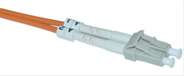
Below is photo of a typical LC fiber assembly commonly used many years ago. This older traditional-style LC assembly has long strain-relief boots and uses a large 3-mm zip cord design where each fiber is contained within its own jacket bonded together. This style was acceptable long ago when density was not a concern.

Today in these very high-density installations, using this style of fiber cabling as shown above is not very practical. Listed below are several modifications made to the traditional LC fiber assembly to help improve the use in these newer higher-density installations.
Smaller O.D. Jackets
One of the first and probably most noticeable change to these fiber assemblies was to reduce the size of the overall fiber cable. Originally, fiber assemblies used two 3.0-mm individual jacket fiber strands bonded together in the assembly. This was okay when density was not a concern, but manufacturers soon discovered that they could shrink the fiber jacket and use a 2.0-mm size. You can see the area advantage in the cross-sectional view below. This improvement provided an approximately 55% area material space reduction.

Uni-Boot Jacket Design
Another design change to LC fiber assemblies was to move away from the traditional-looking "Zip Cord" design and go to what is called the "Uni Boot" jacket design. In the zip cord design method, each strand of fiber is inside its own jacket. The uni-boot design puts both TX and RX fibers into a single overall jacket, further reducing space by 50% more.
The move to 2.0-mm cable jacketing and the switch from zip cord to uni-boot design together greatly reduced the overall material area space in large installations.

Advantages gained by these changes include:
Addition of Pull Tabs
With fiber installation densities up to 144 fiber (72 LCs) in a 1 RU space, removing a LC connector in the middle can be a challenge. See the example of 1RU Fiber enclosure with 72 LC ports.

It's one thing to have the ability to place 72 LCs in 1 RU space, it's another if you have to make a change by removing a fiber cable buried in the middle. With these types of fiber densities, an installer will have difficulty getting to and pressing the release tab on the LC to remove the connector. A solution to this problem was to add a "Pull Tab" to the LC connector. This allows the user to pull on the tab that extends away from the LC connector. When the user pulls on the tab, it releases the latching lock on the LC making it easy to remove. Also, these pull tabs assist with installing an LC fiber cable, too. Because the pull tab extends outward, the installer can use it to help align the nose of the LC connector to the female LC socket.

Labeling
Most people don't give much thought to labeling when it comes to cabling, but when you're working in very dense installations it can be something to consider. Typically, fiber cable assemblies are "crossed" duplex, which is made with two strands of glass each with its own connector held together with a clip. SC and LC fiber assemblies follow this construction. Labels with markings such as A1, A2, B1, B2 are placed on each jacket to help identify this.
Left Side of Fiber Cable Right Side of Fiber Cable
A1 (TX port) ------------------------------------- B2 (RX port)
B1 (RX port) ------------------------------------- A2 (TX port)
There are cases when an installer may want to separate the two connectors on one side and make the fiber cable a straight assembly. If the installer wants to switch back to a crossed assembly or needs to trace the individual fiber on a long assembly, labeling can help assist with this.
Originally years ago, manufacturers used "clip-on" labeling identifiers. They were added by sliding them on to the fiber cable before the connector was terminated. These were okay and not usually any concern in simple installations. But as fiber density became more in demand, the use of "clip-on" labeling was not desired. Mostly because the "clip-on" labels were bulkier and slid around the cable jacket, manufacturers switched to a "sticker" type label, which was much neater-looking and did not slide around.

Bend Insensitive Fiber
Improvements of the glass core is another advancement in the industry over the past several years. Bend Insensitive Fiber (BIF) is an enhancement to the glass core where a very small bend radius can be achieved and still maintain optical performance.
When fiber cabling is bent, the light wavelength traveling through the glass core hits the cladding and changes its direction. This causes some light to escape the core therefore causing (dB) power loss. Bend Insensitive Fiber helps to eliminate this.
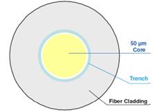
Bend Insensitive Fiber uses an optical "trench," which is added to the cladding area outside of the fiber core. See the cross section of OM3, 50/125-um glass. The optical trench is the term used for a ring of "lower index of refraction material," which was added over the glass core to basically reflect the lost light back into the core of the fiber, reducing the (dB) loss.
Fiber assemblies using (BIF) glass allows installers to achieve a bend radius as small as 7.5 mm.

Smaller Strain Relief Boots
With the greater demand for fiber density, another LC connector improvement manufacturers began to use was smaller strain-relief boots. Normally, the strain-relief boot protects the fiber as it enters the rear of the connector. These historically were longer to protect the bend radius of the fiber glass core. With the need to place more LC fiber assemblies closer and with the enhancement of bend insensitive fiber, manufacturers now can use much shorter strain-relief boots.

By using smaller boots on the LC fiber assemblies, installations can even become neater which helps improve equipment port visibility and airflow throughout the data cabinet.
Reverse Polarity Option
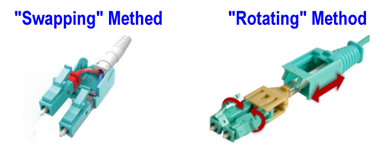
One of the biggest changes to LC fiber cable was the introduction of the reverse polarity feature. This is a feature where the user can swap the left and right LC leads of the connector on the "same" side. This allows the user to convert a standard "crossed" LC fiber assembly to a "straight" LC assembly. There are special applications using MPO cassettes with LC connectors where a user may need to do this.
To reverse the polarity on the cable, manufacturers design a function on the LC connector where a user can modify the connector to flip the LC leads. Some do this by allowing the user to rotate the individual LCs or by opening the connector housing and swapping them. Every manufacturer designs this feature a little differently.

More fiber assembly houses are including this feature on their LC assemblies or are offering a special "premium" LC fiber assembly line with this feature.
Today, the LC fiber assembly with all its modifications is not the same as when it was first introduced to the industry well over twenty years ago. Although its function may remain the same, because of the increased demand and need of fiber optics in the data center along with the greater need for port density, the LC fiber cable has evolved. Smaller cable jackets along with the uni-boot jacket design, plus the use of pull tabs, improved labeling, smaller boots, and reverse polarity are what's needed for high-density high-bandwidth applications today.


Product Engineer
Steve Molek has 27 years’ experience in the cabling and connectivity data communication industry. He started his career as a Technical Support Representative and now works as a Project Engineer for Black Box. As a Product Engineer, his primary focus is evaluating and testing all new cabling and connectivity products for sale by Black Box and training our inside technical support and sales teams. Steve also works directly with our domestic and international OEM suppliers as well as several nationally recognized third-party testing labs. Steve holds a B.S. degree in Mathematics and Computer Science from California University of Pennsylvania and an MBA from Waynesburg University.