In just seven quick steps, take our AV-over-IP video distribution system from a static video wall to a dynamic video wall with switching and control. No additional video wall processor required.
In Part 1, we covered how to set up a static video wall without a video processor. Now it’s time to turn it up a notch and learn how to set up a dynamic video wall with added control and switching.
Recall we started with the MediaCento IPX PoE Multicast 1 x 4 Kit. The kit includes a transmitter, four receivers, a PoE (Power over Ethernet) network switch, and five 2-meter (6.5-feet) locking HDMI cables. Everything you need to multicast HDMI video over an IP network and create static video walls.
In order to make the video wall dynamic, you’ll need to add to the existing system:
The additional sources and transmitters enable additional content to display, and the controller enables you to take full control over the IP-based transmitters and receivers.
Let’s dive right in to the MediaCento multicasting system and get the controller up and running.
Step 1: Connect Additional Transmitters to the Switch and Source In this scenario, we have one additional source, a laptop, so we will need one additional transmitter. Connect the second transmitter to the PoE network switch using a CATx cable. Then, using a locking HDMI cable, connect source – in this case, a laptop – to the transmitter unit.
Step 2: Connect the MediaCento IPX Controller Connect the power supply to the controller and connect it to the network switch using a CATx cable.
Step 3: Access the Controller’s Web Interface Use the Web interface to configure the controller. Open the Web browser, and type the IP address in the address field.
Note: For more details regarding IP addresses, see the user manual included with the controller.
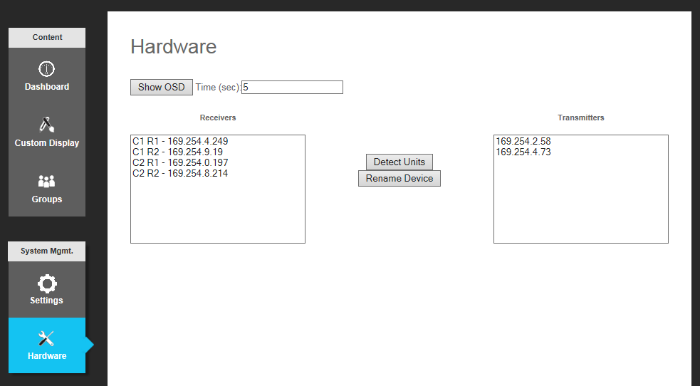
Step 4: Detect Units In the Web interface, go to the Hardware tab and:
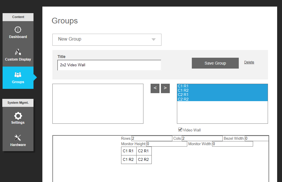
Step 5: Update Group Settings In the Web interface, go to the Groups tab and:
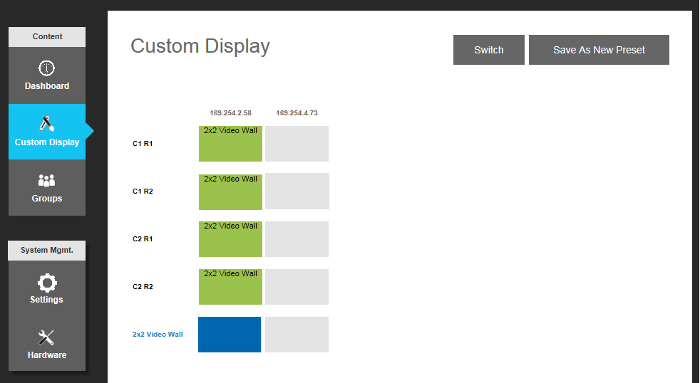
Step 6: Enable Full-Screen Video Wall Still in the Web interface, go to the Custom Display tab and select which source you would like to connect to the grouping that was just created. To switch the iCOMPEL media player to show the video wall across all the screens, click the box in the 169.254.2.58 (the IP address associated with the transmitter connected to the media player) column, 2x2 Video Wall row. Then, click the “Switch” button.
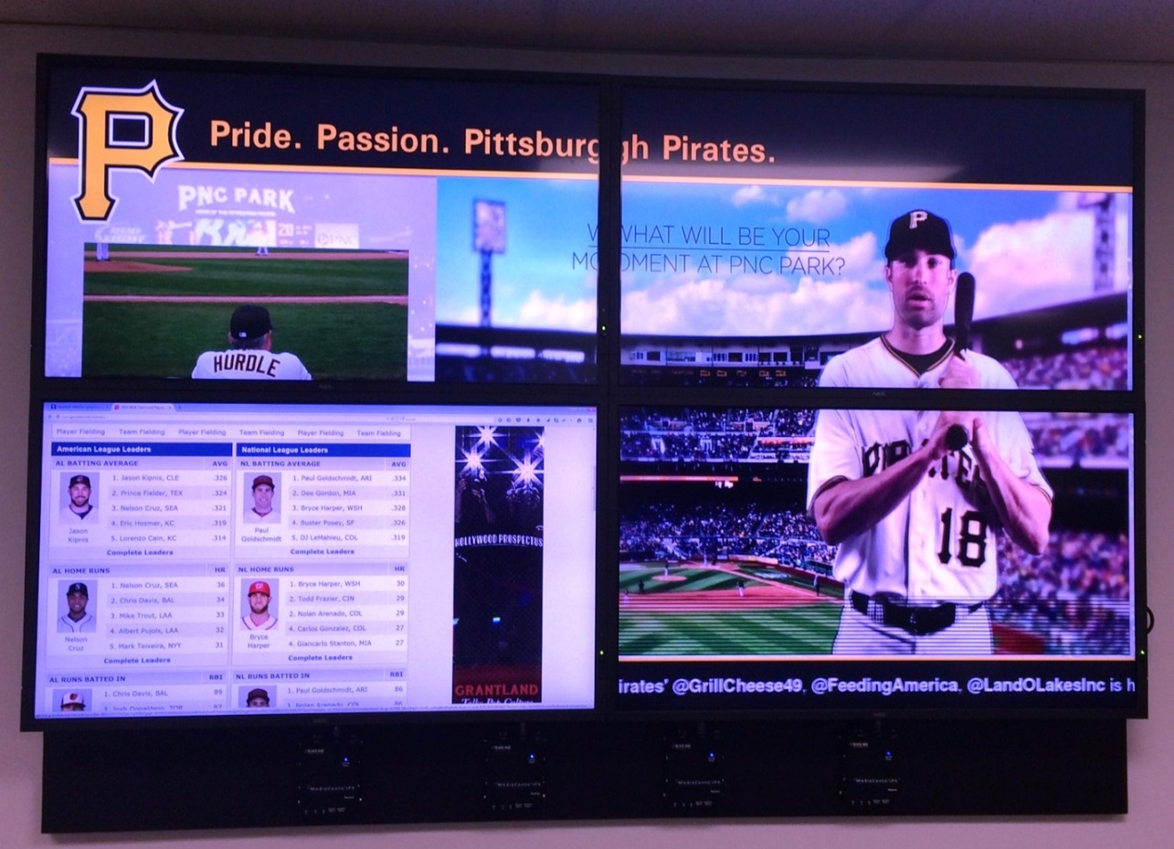
Step 7: Switch Content to Dynamic DisplayTo switch the display from the video wall only to show the source from the laptop in column 1, row 1, click the box in the column with the second transmitter, 169.254.4.73, and click the “Switch” button.
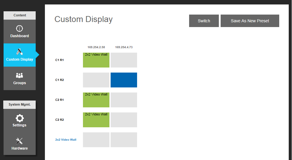
The screen will change to show the content from the second source. In this case, it is pulling content from a Web page.
Still in the Custom Display tab, click the “Save as a New Preset” button to make the configuration available in your dashboard. The dashboard is available on the mobile application; therefore, with the preset defined you can switch and control the displays from your mobile device.
That’s it! In just seven steps we took the static 2x2 video wall and made it dynamic with switching and control. This is just a snippet of the system’s capabilities. The system can create up to 8x8 video walls with 64 screens.
Need help planning your AV solution? Enlist the help of a seasoned AV professional. Contact a Black Box technical engineer at 877-877-2269, or comment below.


