Over the past several years, there has been a major increase in the use of fiber optics in networks. Why? Mainly, the demand for more bandwidth, better security, and longer-distance transmission. The need for fiber in the data center and around the campus are also key drivers of its recent popularity.
In fiber optic installations, the most commonly used components are the fiber optic patch cable assemblies. It is vital that the connectors on these cables are kept as clean as possible at all times because network performance can suffer when they get dirty. However, checking the cleanliness of fiber cable connectors with the human eye is difficult because they are small and hard to see. So, how do you ensure you’re accurately inspecting connectors?
This article will explain how to properly inspect fiber cable end faces. It will also detail the most common ways end faces get dirty and why it’s important to clean them before connecting them to your network.
All fiber patch cable connectors have a ferrule end face where the fiber strand is centered to allow it to mate with another fiber assembly or attach directly to a piece of equipment. If you look at the connector, the ferrule end face is the exposed white ceramic tip of the fiber cable.This tip must be as clean as possible to ensure the best optical results, and you should even check its cleanliness before you install a new fiber cable from the factory into your network infrastructure.
Many users simply assume that the fiber end face is clean when the cabling comes directly from the factory. This is wrong. While production factories polish ferrule end faces with a high level of precision and put a dust cap on them, they may still be dirty or oily.What people do not realize is oils can escape from the plastic dust cap and land on the ferrule end face during storage, which can increase the loss of light.
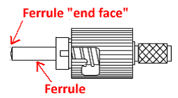
Another common way fiber end faces get dirty is when people take the dust cap off the fiber cable and accidentally touch the ferrule end face, contaminating it and introducing light loss that will affect the overall networking performance.
The good news is these issues can be solved if you perform a final cleaning before you install your assembly. But still, even after this cleaning, how do you know it’s actually clean and ready to use?
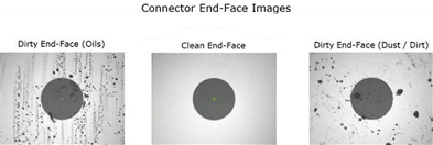
To ensure cleanliness, you can use a microscope that’s specifically made for checking fiber assemblies. These microscopes are normally 100x for multimode and 200x for singlemode inspection. A clean inspection through the microscope typically shows a black dot on a white background.
The image below shows two dirty end faces and one clean end face through a fiber microscope.
However, even if you get what appears to be a clean end face through a microscope, the question still remains: Is it really clean for the high-speed optical networks of today?
To answer this question, inspection microscopes have become more advanced and now use software to scan and take an image of the end face. This process verifies that it is clean and error free for use in optical networks. The software in these microscopes, now more formally known as a tester, follows the accepted testing procedure IEC 61300-3-35 for fiber optic interconnecting devices and passive components.
This IEC testing standard takes a visual image of the end face and separates the area into four zones, as follows:
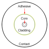

The zones begin from the end face center core and work their way out, forming concentric circles zones. Each circle zone area may be a little different, depending on the type of fiber end face the microscope is inspecting. Let’s review each zone in detail:
Zone “A”: Multimode fiber core is usually 62.5 um or 50 um, so Zone “A” checks from 0 um to 65 um. Singlemode fiber core is usually 9 um, so Zone “A” checks from 0 um to 25 um.
Zone “B”: This is the area outside of zone “A,” and it covers the common area out to 120 um. In Zone “B,” both multimode and singlemode fiber have cladding that covers the glass core.
Zone “C”: This is the very small ring between the outside of the zone “B” cladding area and the beginning of the zone “D” contact area. Zone “C” is important because it’s where all fiber connectors are held in place with epoxy glue to firmly secure the fiber strand to the ferrule. Any unremoved epoxy will be visible here, and, if not removed, could cause an air gap which will attenuate the fiber and increase the light loss.
Zone “D”: This is the outer area that begins from the glue ring in zone “C” and goes out to the farthest area where two fibers could physically meet. This is called the contact area, and you need it to be oil and dirt free since any debris here can create an air gap that causes light loss.
The microscope with the inspection software uses an algorithmic process to check each zone for dirt, oils, excess adhesive/epoxies, and scratches. After inspection, the software will give the end face a final pass or fail result. Any imperfections will be shown on the screen.
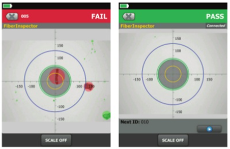
Fiber end face testing can be recorded for each assembly, so you can essentially generate a report that validates every assembly was examined prior to installation. This takes out all the human intervention and guarantees the best optical performance.

Product Engineer
Steve Molek has 27 years’ experience in the cabling and connectivity data communication industry. He started his career as a Technical Support Representative and now works as a Project Engineer for Black Box. As a Product Engineer, his primary focus is evaluating and testing all new cabling and connectivity products for sale by Black Box and training our inside technical support and sales teams. Steve also works directly with our domestic and international OEM suppliers as well as several nationally recognized third-party testing labs. Steve holds a B.S. degree in Mathematics and Computer Science from California University of Pennsylvania and an MBA from Waynesburg University.