Easy to set up. How many times have we heard that phrase in the AV world? And, how can a system with multiple devices, cables, and displays be a simple installation? Well, I’m here to prove it is. In just six quick steps, take our AV-over-IP video distribution system from a packaged box to an impressive, eye-catching video wall. And, there’s no need for an additional video wall processor to do the job.
Start with the MediaCento IPX PoE Multicast 1 x 4 Kit. The kit includes a transmitter, four receivers, a PoE (Power over Ethernet) network switch, and five 2-meter (6.5-feet) locking HDMI cables. Everything you need to multicast HDMI video over an IP network and create video walls. The system is perfect for:
Now it’s time to share how fast you can have the above up and running.
Step 1: Plug in the Switch Plugin the PoE network switch to a power outlet.
Step 2: Connect Transmitter and Receivers to the Switch Connect the transmitter and four receivers to the PoE network switch using CATx cables. The PoE switch eliminates the need for external power supplies, making the installation even easier and more cost-effective. Plus, PoE power offers reliability, flexibility, safety, and scalability.
Step 3: Connect Source to the Transmitter Using the included locking HDMI cable, connect source (i.e., digital signage player, PC, Blu-ray player, DVD player, etc.) to the transmitter unit. Make sure the receivers are on the same channel as the transmitter. If so, the units will automatically connect and video will pass through showing the same video on each screen.
Step 4: Connect the Screens/Monitors to Receivers Using the remaining four locking HDMI cables, connect the screens/monitors to each of the four receivers. NOTE: Sources connected to receiver units will show IP address before connecting.
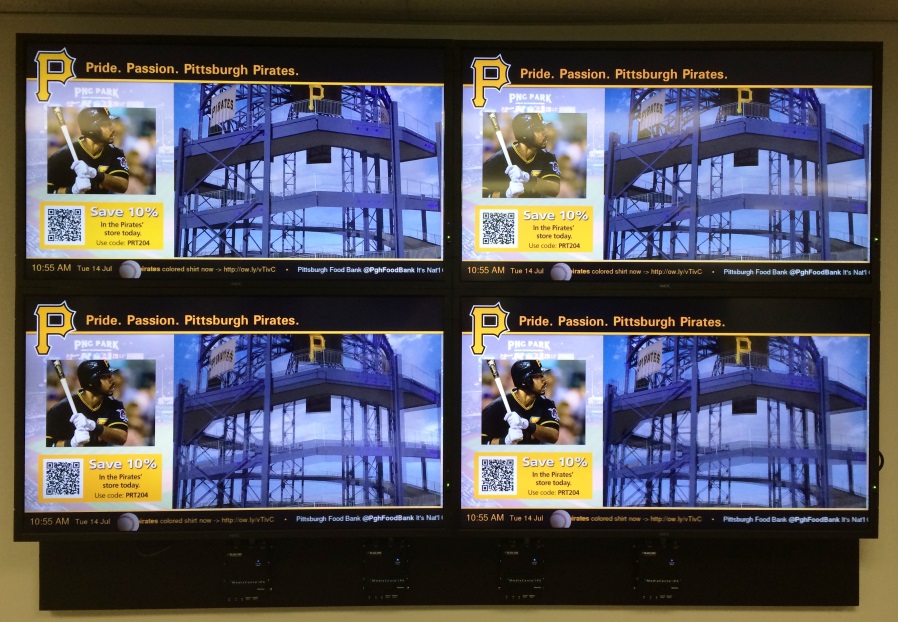
At this point you will have videos on all screens. To get a video wall, you’ll need to access the transmitter settings on the Web, which we’ll do in the next steps.
Video wall example running content from digital signage media player with video and RSS feed.[/caption]
Step 5: Access the Transmitter’s Web Interface Use the Web interface to view information about the device, upload a firmware file to the device, and configure video wall transformers. The Web interface won’t give network information or screen previews.
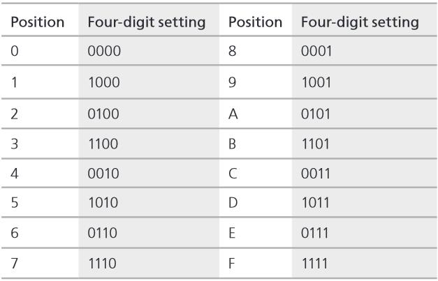
To access the transmitter without an IP address, open a Web browser and insert the address: http://ast-gatewayXXXX.local. The four digits after ast-gateway depend on the position of the rotary switch you’ve set. Please refer to the following table. For example, if the position is set up as 7, then the address should be http://ast-gateway1110.local.
Step 6: Update Settings in the Web Interface In the Web interface, go to the Video Wall tab and:
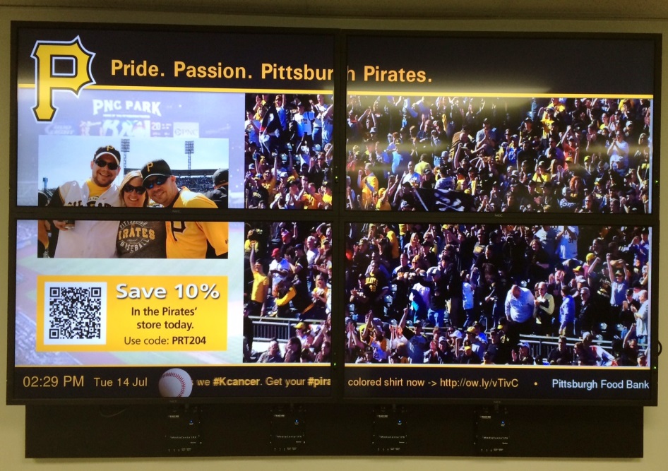
Video wall after changes made in the Web interface. Each display assigned to a receiver.
In part two of this blog post we turn this static video wall into a dynamic video wall with control and switching.


