Knowing your colors can help you understand fiber optics technology. The colors of fiber optic cable and its components play a major part in your installation and understanding how everything goes together. Under normal circumstances, product colors don't affect the product's performance or function, but do provide a good way to identify the type of the product in general. This is very true in the fiber optic world.
A fiber optic cable is made up of four components: the core, cladding, a Kevlar® yarn as the strength member, and a PVC jacket. The core can be comprised of one of two common glass types, multimode fiber optic cable and singlemode fiber optic cable. Each glass type has very specific applications that include data bandwidth and transmission distances, all of which generally cannot be intermixed.
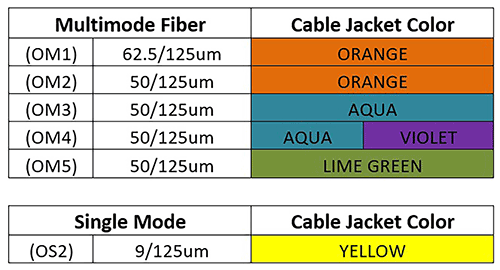
With multimode fiber, there are two common glass cores, 62.5/125-um and 50/125-um. Looking closer at multimode fiber, there is one core type of 62.5/125-um (OM1) and currently four core types of 50/125-um fiber (OM2) through (OM5).
With singlemode fiber, there is only one glass core, a much smaller 9/125-um referred to as (OS2). The fiber glass core for both multimode and singlemode is extremely small: about the size of a human hair and by visual inspection you can't tell one core from another. The glass core rests in the center of the fiber cable.
The second component of a fiber optic cable, a layer of material called cladding, covers the core and is used to contain the light in the glass core. The cladding is built up to 125-um over the glass core.
The third component of a fiber cable, a strength member made up of Kevlar yarn, surrounds the glass core.
The fourth component of a fiber cable is a PVC jacket. One way the industry identifies the type of fiber is by color-coding the PVC cable jacket.
Let's look back to learn why color-coding is relevant: For the first generation of multimode fiber 62.5/125-um (OM1), all cabling jackets were orange. For the next generation of multimode fiber 50/125-um (OM2), the industry kept the same jacket color of orange, but this changed moving forward. For the third generation of multimode fiber optic cable, which still was 50/125-um (OM3), the cable jacket color changed from orange to aqua. This was important because (OM3) fiber was classified as laser-optimized fiber that supported 10-Gbps data transmission. In addition, (OM3) fiber to support 10-Gbps transmissions used VSCEL (Vertical Cavity Surface Emitting Lasers) instead of the LEDs that previous versions of multimode fiber used.
Next came (OM4) fiber, which supported longer distances at the same data transmission. Here is where it gets a bit confusing. We know that OM3 cable had an aqua color cable jacket. At first, the industry also used an aqua cable jacket to identify OM4 fiber, but soon realized that prior and new installations were mixed with OM3 and OM4 fiber both supporting 10-Gbps transmission. Since OM4 fiber supports longer distances than OM3, if both types were aqua color, installers could not know what distance an aqua cable would support. This caused a problem when installers expected any aqua cable to support maximum 10-Gbps distances. The only way to identify the distance difference between OM3 and OM4 cable (both aqua color) was by reading the cable legend. Although some manufacturers used the violet color technically called "Erika Violet" on (OM4) fiber, the market was already becoming saturated with (OM4) as aqua so the industry as a whole did not officially adopt violet as a recognized color for (OM4). Finally, in the latest generation of 50/125-um (OM5), multimode fiber was identified using a lime green jacket color.
Now, when it comes to singlemode fiber optic cable, the jacket color is much simpler to identify. Since there is only one fiber core, 9/125-um, the cable jacket color is always yellow.
For fiber connectors, the color of the connector and housing is also used for identification. This helps identify the connectors used for both multimode and singlemode fiber optic cable, since the glass core varies. The glass core of multimode fiber can be either 62.5-um or 50-um, while singlemode fiber is always 9-um. The common factor for both multimode and singlemode is the cladding that covers the glass core. It's always 125-um.
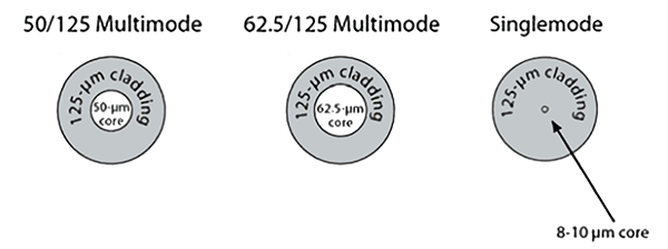
Because the glass core varies between multimode and singlemode with the cladding always being 125-um, the accuracy and precision of the hole in the center of the ceramic tip ferrule of the connector must be very precise. The ferrule is a ceramic tip where the fiber glass passes through. There are two common types of fiber ferrules: UPC (Ultra Polish Connector), which has a standard convex tip used on multimode and singlemode connectors, and APC (Angled Polish Connector), which has an 8-degree angle tip. APC connectors are only used with singlemode fiber cables.
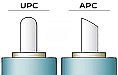
The ferrule is where the cladding travels through as part of the termination process. This hole must always be in the center of the ferrule and its size becomes important, especially when distinguishing between multimode and singlemode fiber applications.
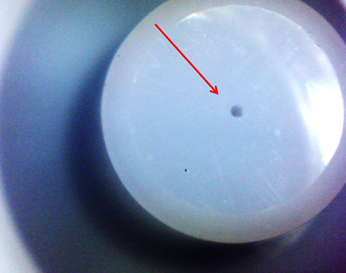
This is important because the larger glass core used for multimode makes it more forgiving when aligning two fibers together. Singlemode has a smaller glass core, and if the center hole is "out of center" the dB loss will greatly increase. So the precision, size, and accuracy of the hole in the center of the ceramic ferrule is extremely important. A more precise hole in the ferrule usually increases the overall cost of the fiber connector.
The center hole in multimode connectors for the ferrule is sized at 126-um or 127-um, which easily lets the 125-um cladding along with the glass core travel through the ferrule. Because multimode has a glass core of 50-um or 62.5-um, a 127-um hole in the ferrule will not hinder the optics. For singlemode connectors, the center hole in the ferrule is typically 125.5-um or even 125-um, which is much closer to the cladding size to best guarantee that the smaller 9-um glass core perfectly aligns, minimizing the amount of overall insertion dB loss. Because of the precision and smaller hole size used for singlemode connectors, the cost of these connectors is more compared to multimode connectors.
The precision and accuracy of the hole in the ceramic tip ensures the hole is as small as possible while aligning the hole in the center of the ceramic tip. Remember the fiber tip at some point will connect or mate with another fiber assembly or a piece of equipment.
With all this being said, the industry uses colors to help identify the connector being used on the raw fiber optic cable. Under normal multimode fiber terminations, the colors of beige, black, and aqua are used. Beige is used for legacy OM1 (62.5-um) fiber termination and black is used with OM2 (50-um) fiber terminations. The color aqua is also used with (50-um) fiber, but only with OM3 and OM4 terminations. Aqua is used to show a difference between the several types of 50-um fiber. OM3 and OM4 fiber terminations use aqua as an identifier since OM3 and OM4 both support the higher speeds essential for 10-Gigabit applications.
Since there is only one type of singlemode fiber, it normally uses blue for identification, but if the singlemode fiber is using an APC connector, then it uses green for identification. This is very important because you cannot mix UPC and APC singlemode connectors together. Remember that the main difference between APC and UPC connectors is the fiber endface. APC connectors (which are color-coded green) feature a fiber endface that is polished at an eight-degree angle; UPC connectors (which are color-coded blue) are polished with no angle. With UPC connectors, any reflected light is directed straight back toward the light source.
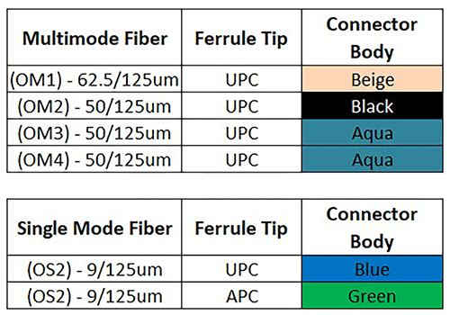
By knowing these basic color identifications for fiber cable jackets and connectors, you can save time and effort. A simple visual inspection quickly reveals what type of fiber assembly and connectivity you are working with. This can help eliminate confusion and possible accidental disconnects with your fiber infrastructure in your data center.
Steve Molek
Product Engineer
Steve Molek has 27 years' experience in the cabling and connectivity data communication industry. He started his career as a Technical Support Representative and now works as a Project Engineer for Black Box. As a Product Engineer, his primary focus is evaluating and testing all new cabling and connectivity products for sale by Black Box and training our inside technical support and sales teams. Steve also works directly with our domestic and international OEM suppliers as well as several nationally recognized third-party testing labs. Steve holds a B.S. degree in Mathematics and Computer Science from California University of Pennsylvania and an MBA from Waynesburg University.